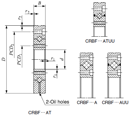
| Model No. | Boundary Dim (mm) |
Mounting Dim (mm) |
Basic load rating |
Mass |
PCD1 mm |
Inner ring Mounting holes (mm) |
PCD2 mm |
Outer ring Mounting holes (mm) |
|||||
|
Inner Ф |
Outer Ф |
Width | |||||||||||
| C | Co | ||||||||||||
| d | D | B | rmin | da | Da | kN | kN | kg | |||||
| CRBF 108 AT | 10 | 52 | 8 | 0.30 | 24.00 | 31.00 | 2.91 | 2.43 | 0.120 | 16 | 4-M3 through | 42 | 6-Ф3.4 through Ф6.5 counter bore depth 3.3 |
| CRBF 2012 AT | 20 | 70 | 12 | 0.30 | 36.50 | 48.50 | 7.60 | 8.37 | 0.310 | 28 | 6-M3 through | 57 | 6-Ф3.4 through Ф6.5 counter bore depth 3.3 |
| CRBF 2512 AT | 25 | 80 | 12 | 0.60 | 46.50 | 58.50 | 8.61 | 10.60 | 0.400 | 35 | 6-M3 through | 67 | 6-Ф3.4 through Ф6.5 counter bore depth 3.3 |
| CRBF 3515 AT | 35 | 95 | 15 | 0.60 | 56.00 | 74.00 | 17.30 | 20.90 | 0.660 | 45 | 8-M4 through | 83 | 8-Ф4.5 through Ф8 counter bore depth 4.4 |
| CRBF 5515 AT | 55 | 120 | 15 | 0.60 | 76.00 | 94.00 | 20.10 | 27.70 | 0.960 | 65 | 8-M5 through | 105 | 8-Ф5.5 through Ф9.5 counter bore depth 5.4 |
| CRBF 8022 AT | 80 | 165 | 22 | 1.00 | 107.00 | 137.00 | 51.10 | 72.00 | 2.630 | 97 | 10-M5 through | 148 | 10-Ф5.5 through Ф9.5 counter bore depth 5.4 |
| CRBF 8022 A | 80 | 165 | 22 | 1.00 | 107.00 | 137.00 | 51.10 | 72.00 | 2.630 | 97 | 10-Ф5.5 through Ф9.5 counter bore depth 5.4 | 148 | 10-Ф5.5 through Ф9.5 counter bore depth 5.4 |
| CRBF 8022 AD | 80 | 165 | 22 | 1.00 | 107.00 | 137.00 | 51.10 | 72.00 | 2.630 | 97 | 10-Ф5.5 through Ф9.5 counter bore depth 5.4 | 148 | 10-Ф5.5 through Ф9.5 counter bore depth 5.4 |
| CRBF 9025 AT | 90 | 210 | 25 | 1.50 | 132.00 | 168.00 | 73.40 | 108.00 | 4.830 | 112 | 12-M8 through | 187 | 12-Ф9 through Ф14 counter bore depth 8.6 |
| CRBF 9025 A | 90 | 210 | 25 | 1.50 | 132.00 | 168.00 | 73.40 | 108.00 | 4.830 | 112 | 12-Ф9 through Ф14 counter bore depth 8.6 | 187 | 12-Ф9 through Ф14 counter bore depth 8.6 |
| CRBF 9025 AD | 90 | 210 | 25 | 1.50 | 132.00 | 168.00 | 73.40 | 108.00 | 4.830 | 112 | 12-Ф9 through Ф14 counter bore depth 8.6 | 187 | 12-Ф9 through Ф14 counter bore depth 8.6 |
| CRBF 11528 AT | 115 | 240 | 28 | 1.50 | 162.00 | 198.00 | 84.30 | 138.00 | 6.810 | 139 | 12-M8 through | 217 | 12-Ф9 through Ф14 counter bore depth 8.6 |
| CRBF 11528 A | 115 | 240 | 28 | 1.50 | 162.00 | 198.00 | 84.30 | 138.00 | 6.810 | 139 | 12-Ф9 through Ф14 counter bore depth 8.6 | 217 | 12-Ф9 through Ф14 counter bore depth 8.6 |
| CRBF 11528 AD | 115 | 240 | 28 | 1.50 | 162.00 | 198.00 | 84.30 | 138.00 | 6.810 | 139 | 12-Ф9 through Ф14 counter bore depth 8.6 | 217 | 12-Ф9 through Ф14 counter bore depth 8.6 |
CRBF Series Crossed Roller Bearings
1. Basic Characteristics
Structural advantages: The bearings come with integrated mounting holes, eliminating the need for separate fixing flanges and support housings. The one-piece inner and outer ring structure with an integrated base means installation has minimal impact on performance, allowing the bearings to maintain stable rotational accuracy and torque. They are suitable for applications involving either outer ring or inner ring rotation.
Core features:
High precision: Available in P2/P4 accuracy grades with rotational runout accurate to 0.001 mm.
High stability: A strictly controlled heat treatment process with multiple tempering cycles relieves internal stress, ensuring outstanding stability.
High rigidity: The unique crossed roller design delivers excellent load-carrying capacity in all directions.
High quality: Manufactured to international standards for strong interchangeability, making them a direct substitute for equivalent products.
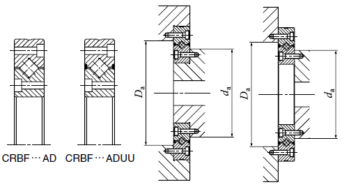
2. Installation Method
Pre-installation preparation: Clean the bearing mounting surface and related components. Inspect the base to ensure it is free of defects, preventing installation issues or failures caused by base problems.
Installation procedure: Place the bearing horizontally onto the base. Position a small flat wooden block or similar material on the bearing surface, then gently tap the block with a hammer to slowly press the bearing into position until it is parallel with the base or can no longer be driven in.
Post-installation inspection: Check the bearing for any installation damage, paying attention to appearance, rotational speed, and whether any noise is present.
3. Running Inspection Procedure
Basic inspection:
Small bearings: Rotate by hand to confirm smooth operation. Identify potential issues such as foreign matter, surface damage, improper installation, or insufficient clearance that may cause abnormal rotation (e.g., uneven rotational torque or excessive torque).
Large bearings: Start the equipment under no load and then shut it off immediately. Use the inertia coasting period to check for vibration, abnormal noise, or friction in rotating components. If no abnormalities are found, proceed to powered running inspection.
Powered running inspection:
Begin with no-load, low-speed operation, then gradually increase to rated conditions. Check for abnormal noise, temperature anomalies, lubricant leakage, or discoloration.
If any abnormality occurs, stop the machine immediately, investigate the cause, and disassemble the bearing for inspection if necessary.
Temperature inspection:
Temperature can be checked by hand on the housing surface or by directly measuring the outer ring temperature through the oil port.
Under normal conditions, the temperature will stabilize and decrease after 1–2 hours of operation. If the temperature rises too rapidly or remains abnormally high, possible causes include excessive lubricant, insufficient clearance, improper installation, severe seal friction, or an inappropriate lubrication method. Prompt corrective action is required.
4. Anti-rust Treatment
Paint selection: Avoid paints containing oxidizing components; solvent-free paints are recommended.
Anti-rust dipping: Small bearings can be immersed in anti-rust grease to form a protective layer on the surface.
Anti-rust brushing: Suitable for construction equipment or specially shaped bearings. Apply the anti-rust oil evenly in an appropriate thickness, avoiding buildup or missed areas.
Anti-rust spraying: Used for large bearings. Apply solvent-diluted or thin-film anti-rust oil. Observe fire safety precautions and wear proper protective equipment.
5. Application Fields
Primarily used in high-precision machine tools, medical devices, and robotics.